Core Principles and Technological Enablers
In near-field wireless power transfer (WPT) applications, the inverter plays a fundamental role by converting DC power into high-frequency AC voltage and current. The choice and architectural design of the inverter directly dictate system power transfer efficiency, thermal management demands, package size, and load adaptability.
To achieve optimal performance at required radio frequencies, switched-mode power amplifiers are highly preferred due to their high intrinsic efficiency. Modern advancements in this domain are heavily driven by wide bandgap (WBG) semiconductors, explicitly Silicon Carbide (SiC) MOSFETs and Gallium Nitride (GaN) transistors, which enable efficient energy transfer at elevated operating frequencies with minimised switching losses.
Primary Inverter Class Architectures
Class-D Inverters
Utilises a pair of switches operating in a push-pull configuration to drive the load through resonant tank circuits. This topology offers extreme simplicity and high efficiency, rendering it highly favorable for mid-power applications.
Class-E Inverters
Deploys a single switch combined with a carefully designed shunt capacitor and resonant network to shape voltage and current waveforms. This architecture achieves soft-switching conditions to successfully minimise switching stresses and losses, offering excellent efficiency and structural ease of implementation in single-ended configurations.
Class-DE Inverters
Serves as a structural extension of the Class-E concept, incorporating dual switches operating out-of-phase. This layout enhances absolute power handling capabilities while simultaneously reducing voltage stress on the components.
Statistical Distribution and Application Limits
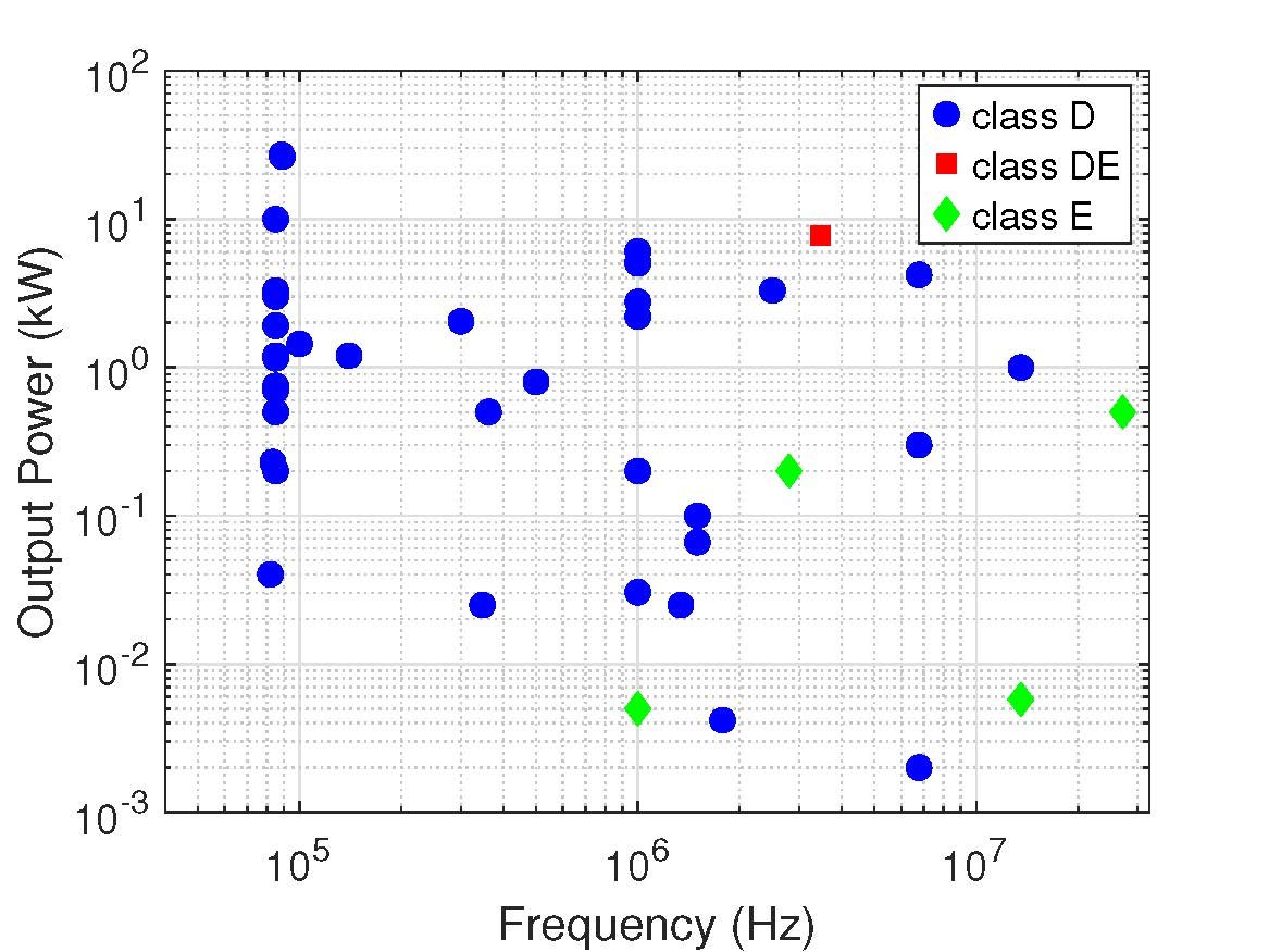
A comprehensive review of recent literature shows that approximately 90% of WPT studies utilise Class-D inverters for DC-AC conversion. This overwhelming dominance stems from key performance indicators including high controllability, excellent robustness under load variations, and the feasibility of achieving soft-switching operation. Class-D is exceptionally prevalent in both Inductive Power Transfer (IPT) and Capacitive Power Transfer (CPT) designs ranging from 2 W up to multi-kW regimes, spanning frequencies from tens of kHz up to a few MHz, and delivering power levels up to 27.08 kW.
However, when operating frequencies scale above 10 MHz, Class-D inverters encounter severe switching losses, making them less favorable. At these higher limits, Class-E topologies (representing ~5% of reviewed papers) become highly viable, operating at frequencies such as 27.12 MHz. While Class-E circuits achieve superb high-frequency efficiency across smaller bands (e.g., 13.56 MHz and 2.8 MHz), they are fundamentally bounded by restricted output power handling (typically below 500 W) and display high sensitivity to load variations.
To bridge this gap and combine high high-frequency efficiency with heavy power delivery, Class-DE configurations are employed. These have demonstrated output power performance up to 7.8 kW at an operating frequency of 3.47 MHz, though they demand considerably more complex system design methodologies.