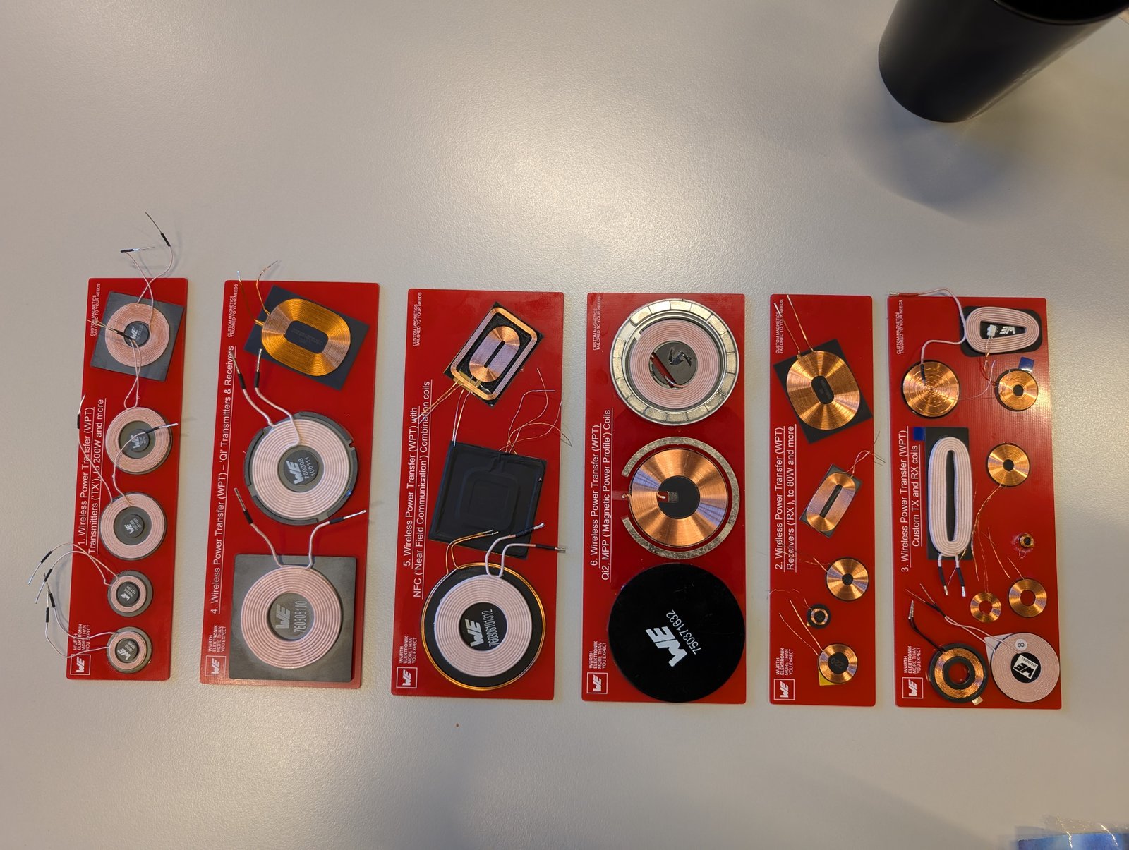
Couplers for IPT
The coupler is the core of a WPT system: it gives the system its wireless capability and strongly impacts the performance of the entire WPT system. On this page, we first look at the theoretical models used to describe the coupler, to gain insight into its key performance indicators. Afterwards, we discuss how inductive couplers have developed over time and how their designs evolved for different applications.
At a glance
Couplers are the magnetic link that enables wireless power transfer in IPT systems.
- Key idea: Energy is transferred through magnetic coupling between two coils.
- Power: From small devices to high-power EV and industrial systems.
- Applications: Monorails, AGVs, factory automation, and EV charging.
- Designs: Circular, DD, DDQ, BP, and three-phase couplers.
Models for inductive link
The models that describe couplers for IPT systems are derived from classical, linear transformer theory. The two most prevalent modeling approaches are: (1) the coupled inductor model, and (2) the T-model.
(1) Coupled Inductor Model
The coupled inductor model represents the coupler as a two-port network, where the impedances are modeled as inductors. The governing equations for this model are:
According to Ampère's and Faraday's laws, an alternating primary current \(i_\text{P}(t)\) in the Tx coil generates a time-varying magnetic field, inducing a secondary voltage \(v_\text{S}(t)\) in the receiver coil. When a load is connected, a secondary current \(i_\text{S}(t)\) flows.
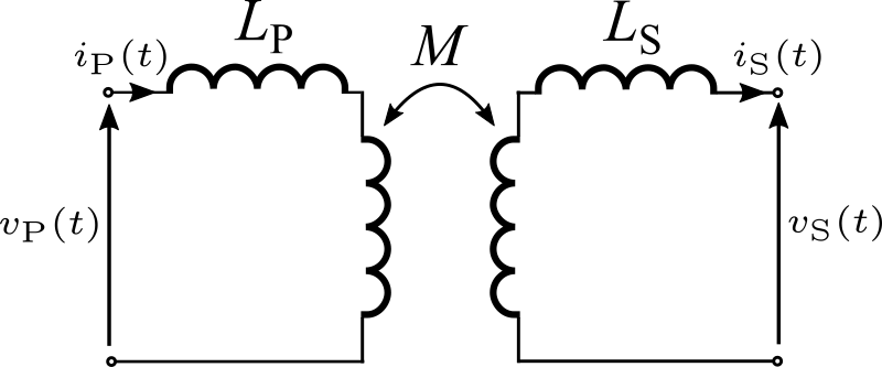
The system is characterized by three parameters: the primary self-inductance \(L_\text{P}\), the secondary self-inductance \(L_\text{S}\), and the mutual inductance \(M\). These parameters are determined through open- and short-circuit voltage tests, which measure the secondary open-circuit voltage \(V_\text{oc}\) and short-circuit current \(I_\text{sc}\). The product of these values indicates the amount of power that can be transferred, i.e., the maximum VA rating:
However, this quantity does not represent a physically realizable operating point, as \(V_\text{oc}\) and \(I_\text{sc}\) cannot occur simultaneously. Instead, \(P_\text{su}\) serves as an indicative measure of the maximum energy transfer capability associated with a given coupler.
To quantify the magnetic coupling between the primary and secondary windings, the inductive coupling coefficient \(k_\text{I}\) is defined as:
(2) T-Model
An alternative representation is the T-model. This model incorporates the primary and secondary leakage inductances \(L_1\) and \(L_2\), the mutual inductance \(L_\text{m}\), and the turns ratio \(n\) of a transformer with solid-round wire windings.
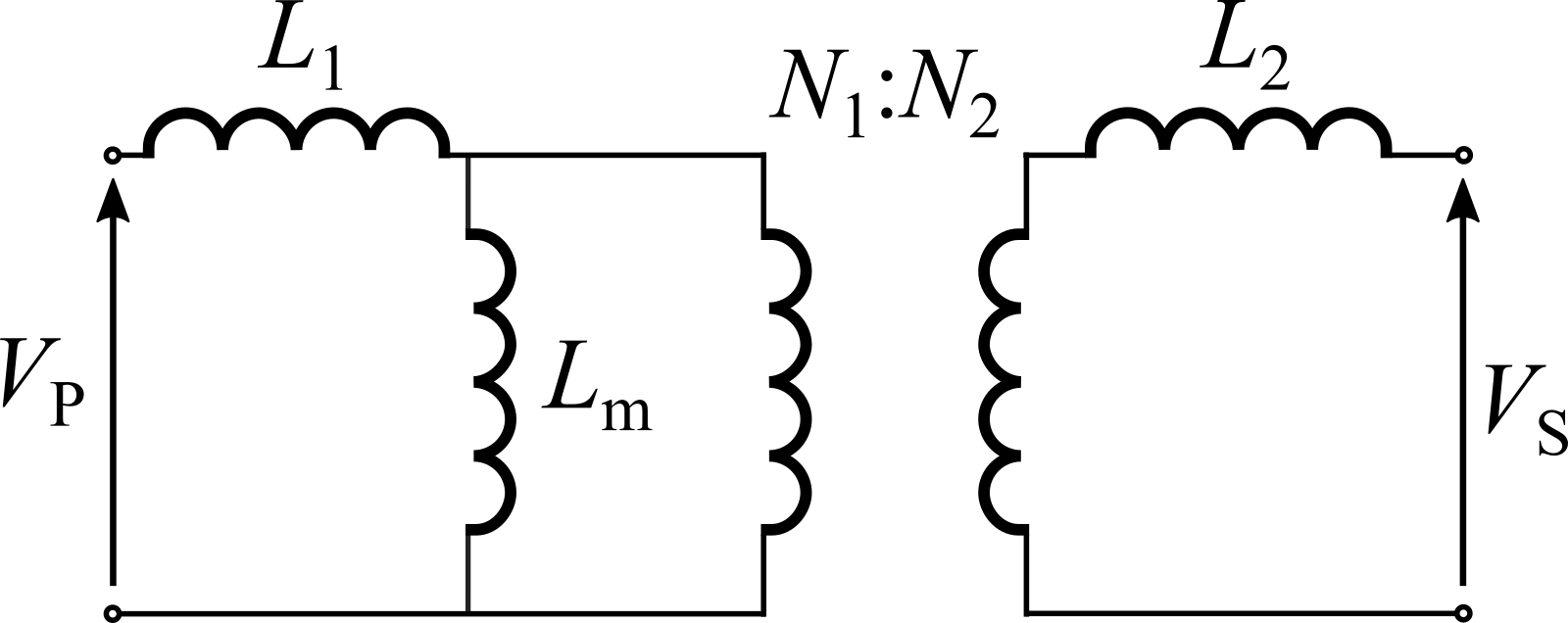
The leakage inductances \(L_1\) and \(L_2\) account for the leakage flux that does not contribute to energy transfer. In contrast, the mutual inductance \(L_\text{m}\) represents the portion of the magnetic flux that is effectively coupled between the coils. The ideal transformer component of the model reflects the turns ratio.
As in the coupled inductor model, the same coupling coefficient can be defined:
The inductive parameters used in the coupled inductor model and the T-model are not directly equivalent, although they are interrelated (compare the two equations for \(k_\text{I}\)!).
It should be noted that IPT coupler models typically originate from a linearly coupled inductor or T-model, but the parameters are usually computed using finite element analysis (FEA) tools or approximated through analytical formulas.
General Coupler Topologies for IPT
Because couplers are application-oriented, this section discusses IPT couplers for the applications of (1) monorails and (2) wireless electrical vehicle (EV) charging. As these two main applications demand high power, the coupler topology design are essentially the basis for the design of IPT couplers for other applications.
(1) Monorail systems
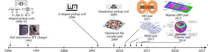
The monorail application consists of a single conductor as transmitter. The receivers can be one or more coils. As can be seen in Figure X, between 1990 and 2005, the focus was mainly on this IPT application. Possible industries that use this technology are clean factory automation, AGV, and the railway sector.
The research focuses on capturing the magnetic field to maximize the coupling \(k_\text{I}\) and the transferable apparent power. Many pickup configurations are I, E, flat E, and S shapes.
In another approach, a coil is added perpendicular to an E pickup, resulting in a quadrature pickup that captures both vertical and horizontal flux and is therefore more tolerant to misalignment.
(2) Wireless EV charging
To enable wireless EV charging, several design modifications had to be made:
- the power had to be increased to make IPT suitable for EV applications,
- field emissions had to be limited due to the proximity of people to the couplers, and
- the transfer distance had to be increased to efficiently transfer power from strongly coupled to loosely coupled systems.
Because a larger coupler surface area captures more flux and therefore more power, couplers were initially enlarged. Although inductive charging concepts already existed in the 1990s, research into coupler optimization did not shift until the 2000s.
First, a flattened circular pad was developed, optimizing ferrite usage, field shielding, and flux capture. Optimized design methodologies employ objectives such as coil-to-coil efficiency and surface power density, coupling efficiency and quality factor, or coil-to-coil efficiency and leakage field.
To create more compact and cost-efficient designs, the Double D (DD) and Double D-Quadrature (DDQ) pads were developed. These polarized topologies concentrate the magnetic field, increase maximum VA rating \(P_\text{su}\), and improve misalignment tolerance. These properties also make DD and DDQ pads suitable for dynamic EV charging.
However, a circular pad has a higher magnetic coupling than DD, DDQ, and BP, which translates into a higher power density. Design methodologies such as those presented in the literature employ multi-objective optimization to simultaneously enhance coil-to-coil efficiency, power density, misalignment tolerance, and ferrite utilization.
A variant is the Bipolar (BP) pad, in which the two D coils are mutually decoupled to avoid mutual induction. BP offers similar advantages to DDQ but is more cost-efficient than circular pads. Various approaches optimize the coupler design either based on VA rating \(P_\text{su}\), or through multi-objective strategies that account for core and conductor losses, misalignment tolerance, and design cost.
Finally, three-phase pads were investigated that combine the advantages of DD, DDQ, and BP. To make the WPT system rotationally tolerant, various three-phase coupler topologies have been proposed, including trifolate and tripolar.
The latter configuration consists of three coils that, similar to BP, partially overlap and together form a circular structure. Their main advantages are high rotational tolerance and lower current per conductor.
To further increase the transferable power, Oak Ridge National Laboratories developed the polyphase pad by placing two tripolar pads \(60^\circ\) shifted above each other. This configuration achieves powers of up to \(270~\text{kW}\). Optimization of the primary current improves coupling efficiency under misalignment conditions and reduces leakage flux.
Sources
Document based on:
- A. Cloet, H. Farbakhsh, M. Kleemann, and B. Minnaert, “Recent Advancements in Technologies, Applications, and Regulations of Near-Field Wireless Power Transfer,” in IEEE Access, vol. 14, pp. 49285–49310, 2026, doi: 10.1109/ACCESS.2026.3674000.