Couplers for CPT
The coupler is the part of a wireless power transfer system through which energy is transferred between the transmitter and receiver. In capacitive wireless power transfer (CPT), this coupling is established through the electric field between conductive surfaces rather than through the magnetic field between coils. The coupler dimensions and transfer gap strongly influence coupling, misalignment tolerance, electromagnetic exposure, and overall transfer performance.
On this page, we first introduce the electrical models used to describe capacitive couplers. These models range from simple representations that are convenient for system-level analysis to more detailed models that account for leakage and cross-coupling capacitances. Afterwards, the main CPT coupler topologies reported in the literature are discussed, together with their main advantages and limitations.
At a glance
CPT couplers use conductive plates or surfaces to establish capacitive coupling between the transmitter and receiver.
- Key idea: Energy is transferred through an electric field between conductive surfaces.
- Coupler: Typically consists of flat or concentric conductive plates.
- Key parameter: The capacitive coupling coefficient \(k_\text{C}\) quantifies the degree of capacitive coupling between the primary and secondary sides.
- Main models: Simple CPT model, π-model, and two-port model.
- Main topologies: Parallel four-plate, staggered four-plate, two-plate, six-plate, five-plate, matrix, and concentric couplers.
- Main design challenges: Transfer distance, misalignment, leakage and cross-coupling, electric-field exposure, and circuit complexity.
Models for capacitive link
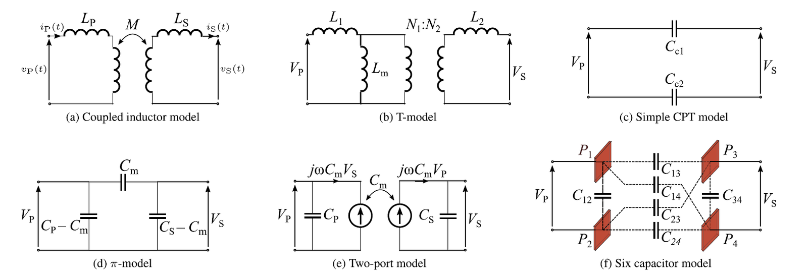
In CPT systems, the electric field between conductive surfaces allows the coupler to be modeled using capacitors. The appropriate model depends on the physical structure of the coupler and on the required modeling accuracy.
Three commonly used approaches are the simple CPT model, the π-model, and the two-port model.
(1) Simple CPT Model
The simple CPT model represents each pair of conductive plates as a capacitor. Because of its simple structure, this model can be integrated rapidly into an overall CPT system model and is therefore convenient for straightforward system-level analysis.
However, the simplified representation has important limitations. First, it neglects cross-coupling effects and leakage fields between different plate pairs. Second, it does not allow the secondary side to be analyzed independently. These simplifications reduce the accuracy of the model when parasitic and cross-coupling effects become important.
(2) π-Model
To account for the additional capacitive interactions between different conductive plates, the π-model incorporates both leakage capacitances and cross-coupling capacitances.
In the six-capacitor representation, the leakage fields are represented by \(C_{12}\) and \(C_{34}\), while the cross-coupling effects are represented by \(C_{14}\) and \(C_{23}\).
The primary and secondary equivalent capacitances can then be determined by short-circuiting the secondary and primary sides, respectively.
These equivalent capacitances can be used to characterize the capacitive coupling between the transmitter and receiver sides.
Capacitive Coupling Coefficient
Similar to the coupling coefficient used for inductive couplers, a capacitive coupling coefficient can be defined to quantify the degree of capacitive coupling between the primary and secondary sides of a CPT system.
The coupling coefficient \(k_\mathrm{C}\) provides an indication of the strength of capacitive coupling and therefore gives insight into the potential energy-transfer capability between the transmitter and receiver sides of the CPT system.
(3) Two-Port Model
The paper also identifies the two-port model as one of the commonly employed approaches for representing CPT couplers. This representation provides a two-port description of the capacitive coupling between the primary and secondary sides and can be used when a more general network representation is required.
The appropriate level of model complexity depends on the intended analysis. The simple CPT model is convenient for rapid system-level modeling, whereas models that explicitly represent leakage and cross-coupling capacitances provide a more detailed description of the physical coupler.
General Coupler Topologies for CPT
CPT couplers typically employ flat or concentric conductive plates. These structures simplify manufacturing and provide flexibility in designing the physical interface between the transmitter and receiver. Different topologies have been proposed to address requirements such as coupling strength, misalignment tolerance, electric-field shielding, safety, and mechanical integration.
(1) Parallel Four-Plate Coupler
The parallel four-plate structure is one of the most intuitive CPT coupler configurations. The transmitter and receiver each consist of two conductive plates with opposite polarity.
This arrangement provides a reasonable capacitive coupling coefficient \(k_\mathrm{C}\). However, lateral misalignment between the transmitter and receiver increases the effective Tx–Rx distance. This increases cross-coupling and consequently reduces the capacitive coupling coefficient.
(2) Staggered Four-Plate Coupler
The staggered four-plate topology places two smaller plates within the electric field generated by two larger plates.
This configuration provides a more compact structure and improved tolerance to rotational misalignment compared with the parallel arrangement.
The main disadvantage is a lower capacitive coupling coefficient \(k_\mathrm{C}\) compared with the parallel configuration. This is attributed to the increased leakage capacitances associated with the staggered arrangement.
(3) Two-Plate Coupler
In the two-plate topology, the transmitter and receiver each consist of a single conductive plate. The return path is provided by another conductive structure, such as ground or a rail track.
This arrangement simplifies the hardware and can reduce the number of conductive elements required for the coupler. However, the configuration requires compliance with touch-voltage limits defined by applicable standards.
(4) Six-Plate Coupler
The six-plate topology extends the parallel four-plate configuration by adding shielding plates at both the transmitter and receiver.
The shielding plates reduce electric-field emissions and can help the system comply with regulatory limits. The topology also supports high-voltage operation, with reported operation up to several kilovolts.
The main drawback is the increased complexity of its equivalent circuit. A six-plate coupler can involve as many as 15 capacitive couplings.
(5) Five-Plate Coupler
The five-plate topology reduces the material and structural complexity of the six-plate configuration by using only one shielding plate.
The trade-off is that the safety zone associated with the electric field is located farther from the coupler compared with the six-plate topology.
(6) Matrix Coupler
Misalignment generally reduces capacitive coupling in CPT couplers. To address this limitation, a matrix coupler structure has been proposed.
The matrix structure can provide strong coupling and maintain acceptable performance under misalignment. However, this approach requires more complex control because the appropriate plates must be selected depending on the receiver position.
(7) Concentric Coupler
Concentric coupler topologies provide another approach to capacitive power transfer. In this configuration, concentric conductive structures are used to transfer power to rotating devices without requiring sliding electrical contacts.
This provides a relatively simple coupler arrangement for rotating systems.
Typical applications include power transfer through bearings, supplying energy to the rotor of a synchronous motor, and powering embedded sensors.
Design Considerations
Although the physical structures differ, misalignment generally reduces capacitive coupling across CPT coupler topologies. Therefore, coupler design involves a trade-off between coupling strength, mechanical arrangement, electric-field exposure, misalignment tolerance, and implementation complexity.
The choice of topology should consequently be made according to the requirements of the intended application rather than based solely on maximum coupling.
Sources
Document based on:
- A. Cloet, H. Farbakhsh, M. Kleemann, and B. Minnaert, “Recent Advancements in Technologies, Applications, and Regulations of Near-Field Wireless Power Transfer,” IEEE Access, vol. 14, pp. 49285–49310, 2026, doi: 10.1109/ACCESS.2026.3674000 .