Foundational Role & Core Objectives
In IPT systems, compensation networks are fundamental to achieving high efficiency, stable power transfer, and regulatory compliance. The inherent inductance of the transmitter and receiver coils introduces reactive components that, if left uncompensated, lead to reduced efficiency, increased voltage and current stresses, and poor controllability.
Specifically, compensating the receiver coil’s inductance maximizes power transfer efficiency by aligning impedance matching conditions, while compensating the transmitter coil reduces the apparent power (VA rating) required from the power source, thereby optimizing input power utilization.
Classic Topologies: Series and Parallel Schemes
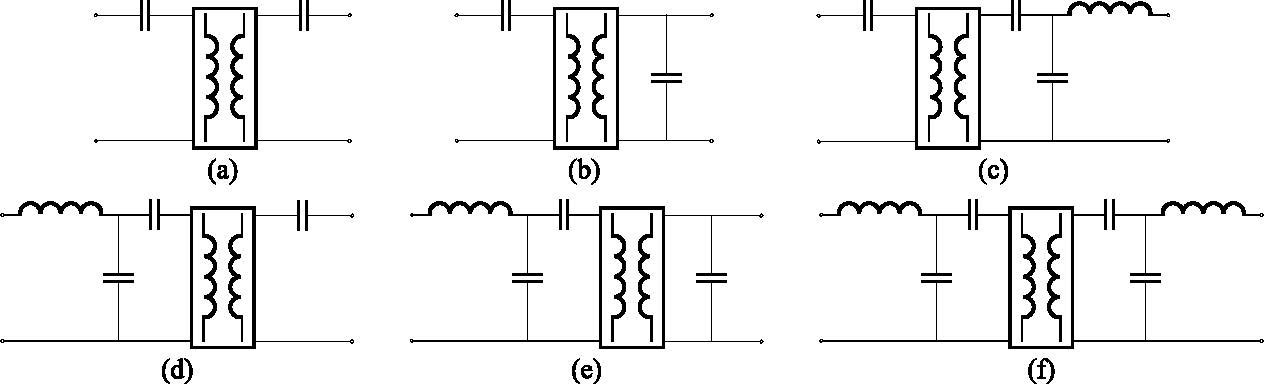
Six representative compensation topologies are commonly employed to address these challenges. These include the basic series-series (S–S), series-parallel (S–P), and more complex hybrid and LCC-based schemes.
The classic S–S and S–P configurations feature capacitors connected in series or parallel to the transmitter and receiver coils, respectively. The S–S configuration ensures that both sides resonate in series, providing stable power transfer even with varying coupling or load conditions, making it a robust choice in many applications. On the other hand, the S–P topology introduces parallel resonance at the receiver side, which can cause load-dependent reactance reflection back to the transmitter, potentially complicating system tuning.
Advanced LCC-Based Network Topologies
To overcome some of the limitations of these basic topologies, advanced compensation networks such as S–LCC, LCC–S, LCC–P, and LCC–LCC have been introduced. These LCC-based networks integrate additional inductors and capacitors, forming more flexible impedance networks that enhance misalignment tolerance, broaden operating conditions, and mitigate electromagnetic interference (EMI). However, it is worth noting that alternative approaches, such as the use of variable-capacitor techniques, have also been proposed for compensating coil misalignment.
In particular, the LCC–S configuration applies LCC compensation on the transmitter side while maintaining series compensation on the receiver, simplifying frequency control and improving power transfer characteristics under varying conditions. The LCC–LCC topology, with LCC compensation on both sides, offers even greater tunability and resilience to coupling variations but at the cost of increased circuit complexity and component count.
Control Advantages and Engineering Trade-offs
One key advantage of LCC topologies, especially LCC–S and LCC–LCC, is that their power transfer characteristics are unimodal with respect to frequency and quality factor, in contrast to the dual-peak behavior observed in the S–S topology. This makes controller design, particularly when using frequency modulation, more predictable and manageable. Furthermore, LCC compensation networks can significantly reduce stray magnetic fields and conducted emissions, aiding compliance with EMI and electromagnetic field (EMF) safety standards.
Nevertheless, the addition of more passive components in LCC networks increases bulk and cost, making them more suitable for high-power transfer applications where efficiency and robustness outweigh size constraints. Their tunability, especially through capacitor parameter adjustment rather than frequency tuning, allows WPT systems to maintain rated power delivery across a broad range of coupling and alignment conditions. Overall, compensation networks are indispensable not only for optimizing efficiency and controllability but also for enhancing the reliability and practical deployability of modern WPT systems.