Essential Role and Impedance Optimization
In CPT systems, compensation networks are essential due to the inherently low coupling capacitance between the transmitter and receiver plates. This low capacitance results in high capacitive reactance, which significantly impedes the efficient flow of current and limits power transfer.
To overcome this, compensation networks, consisting of inductors and additional capacitors, are introduced to cancel out the reactive components and achieve resonance at the operating frequency. By doing so, the system’s impedance becomes predominantly resistive, allowing for more efficient energy transfer, reduced power losses, and improved voltage and current regulation. Consequently, the use of compensation networks enhances the overall performance, efficiency, and stability of CPT systems, especially in scenarios involving weak coupling or variable load conditions.
L and LC Compensation Architectures
L Compensation
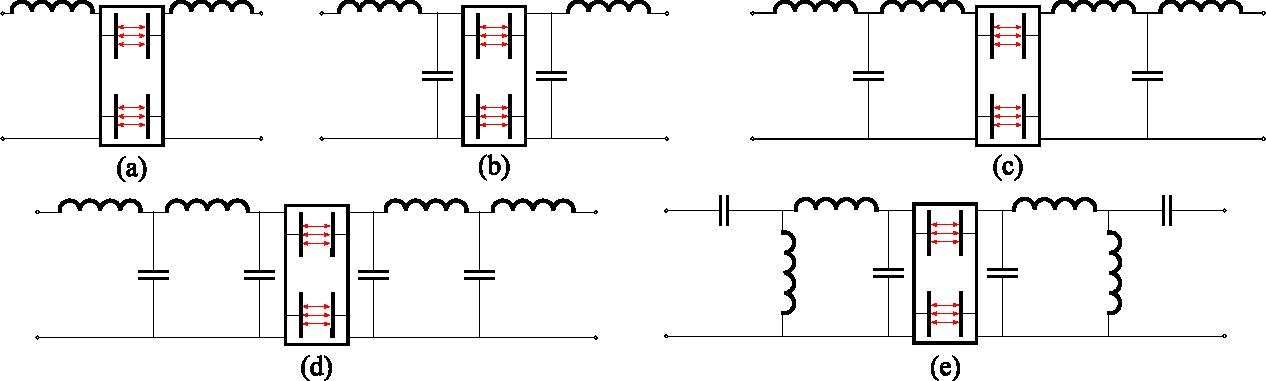
L compensation is a simple method used in CPT systems, where a single inductor is placed in series with the coupling capacitor to achieve resonance. This cancels out the capacitive reactance, reducing impedance and improving power transfer efficiency. While easy to implement and cost-effective, it offers limited tuning flexibility and performs less efficiently under variable loads or weak coupling.
LC Compensation
An effective approach to overcoming the issue of low mutual coupling capacitance in CPT systems is to add additional capacitors in parallel with the coupling plates. This enhances the overall equivalent capacitance, enabling wider air gaps between the plates and making the system less sensitive to changes in distance. Importantly, even when the mutual capacitance remains constant, the equivalent coupling capacitance, and consequently the resonance frequency, stays largely unaffected. This makes the topology well-suited for medium to high-power CPT applications and constant output power subject to physical misalignment.
Higher-Order Resonant Topologies
LCL Compensation
An LCL compensation network is applied on the primary side to eliminate the need for compensation components on the receiver side. This approach reduces the size of the receiver and simultaneously achieves a constant current (CC) output.
LCLC and CLLC Topologies
In addition to the aforementioned compensation networks, LCLC and CLLC topologies have been adopted in recent studies for applications involving large air gaps and high power levels. This is due to the system power being directly proportional to the coupling coefficient.
Impedance-Based, Symmetrical, and Hybrid Topologies
Furthermore, impedance-based compensation networks have been explored in CPT systems. For example, the Z-impedance topology features a symmetrical Z-shaped configuration composed of two identical inductors and capacitors, which provides advantages under short-circuit and open-circuit conditions. The F-type topology, resembling the letter ‘F’, includes a resonant capacitor and two inductors, and is advantageous in scenarios involving sudden load variations.
Hybrid compensation networks have also been reviewed in the literature. For instance, the LC-CLC network was proposed to enhance performance under coupler misalignment, while the LCL-L network aims to minimize the number of resonant components and improve overall system performance.